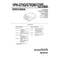
INPUT LEVEL IMIC I 1 IN dBV
COMPRESSION SYSTEM INPUT-OUTPUT CHARACTERISTICS FIGURE 1 Gated Memory Threshold: -90.5 dBV typical at maximum input gain (mic); -40.5 dBV typical at maximum input gain (line) Recovery: In "hold" position, less than 20 dB gain recovery after 1 minute VU Meter Dual-range, 3-function (output level in dB, gain reduction in dB, battery check), illuminated (ac operation only) Gated MemorylPeak Indicator With meter switch in VU position, lights 6 dB below clipping; with meter switch in Comp position, lights when gated memory is "holding" Noise Equivalent lnput Noise: - 129 dBV (low-impedance microphone, 150 ohms, 300 to 20,000 Hz) into 600-ohm load at full gain Equivalent lnput Hum and Noise: -127 dBV (lowimpedance microphone, 150 ohms, 20 to 20,000 Hz) into 600-ohm load at full gain Output Noise: -77 dBV maximum (output control full counterclockwise [off]), -40 dBV maximum (output control full clockwise [on]) (input control down, 300 to 20,000 Hz) Output Hum and Noise: -75 dBV maximum (output control down), -38 dBV maximum (output control up, input control down, 20 to 20,000 Hz) Distortion 0.4% THD, 30 to 20,000 Hz at + 15 dBm output; 0.5% or less IM distortion at + 15 dBm output into 600 ohms Common Mode Rejection 65 dB minimum with input of -20 dBV at 100 Hz Control Interaction Less than 1 dB with any control combination Overload and Shorting Protection Shorting outputs, even for prolonged periods, will cause no damage; microphone input will not be damaged by signals up to 3V Low-Cut Filters 6 dB per octave rolloff at 150 Hz Phase All outputs in phase with respect to all inputs. Pin 2 is "high" with respect to pin 3; pin 1 is ground. Tip of mix bus jack in phase with pin 3. Tip and ring of headphone jacks in phase with pin 2 Tone Oscillator 1 kHz; + 15 dBm minimum at line output with output level full up Phantom Power 30 Vdc nominal, 3.3k series resistance, automatically disabled with input switch in Line position Operating Voltage Ac Operation: 120 or 240 Vac -r-10% (internally selectable), 50160 Hz, 5.5W
Dc Operation: 27 Vdc nominal at 27 mA typical no-signal, 30 mA typical at 0 VU ( + 4 dBm) output; 21.5 Vdc minimum; battery life approximately 10 hours with alkaline batteries at + 4 dBm output in continuous use; three 9-volt batteries, type NEDA 1604A (Duracell MN1604 or Eveready 522 recommended) Temperature Range Operating: -18O to 57OC (0° to 135OF) Storage: -2g0 to 71°C (-20° to 160°F) Dimensions 79.5 mm H x 310 mm W x 230 mm D (3-118 in. x 12-7132 in. x 9-1132 in.) Weight Net: 2.75 kg (6 Ib 1 02) Packaged: 3.25 kg (7 Ib 3 oz) Certifications Listed by Underwriters Laboratories Inc.; listed by Canadian Standards Association as Certified
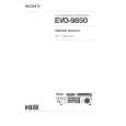
CONTROLS AND CONNECTORS Power Off-On Switch: applies power to the FP51 circuitry. Channel Levellcue Rotary Controls: adjust individual input channel signal levels. Each channel can be cued by pulling the control knob outward to the detent position, rotating the knob to the desired level, and pushing the knob inward to activate 'the channel. Lo Cut Filter Slide Switches: reduce unwanted low-frequency signals such as wind noise by 6 dB per octave at 150 Hz. Master Rotary Control: determines mixed output level at output connector. The control also sets the tone oscillator level when the Tone Osc switch is turned on. Gated MemorylPeak LED: indicates, in gated memory mode, that gated memory is "holding" prior amount of compression during a low input signal, and turns off when input signal is above compression threshold. In peak mode, the LED indicates approaching program overload. It is activated by the shortest transient peak, but remains on long enough to provide easy recognition. The chart below shows the effect of Compressor and Gated Memory switches on indicator operation. GATED MEMORYIPEAK LED FUNCTIONS
Gated Memory off
Compressor out Compressor in
I
Gated Memory on
No operation Gated memory
VU Meter: indicates 0 VU with a + 4 dBm output (recommended for normal use to provide approximately 14 dB headroom from operating level to clipping level) with VUlComp switch in VU position. Rear-panel VU Range +41+8 slide switch permits changing to 0 VU = + 8 dBm. With VUlComp switch in Comp position, indicates compression due to input signal above threshold (lower meter scale). The VU meter is lit during ac operation only; therefore, the illumination serves as a visual alarm if the ac is interrupted and the unit has automatically switched to battery operation. Batt Check Momentary Push-button Switch: operates in conjunction with the VU meter to indicate battery condition. With the Power switch on and the switch depressed, a new set of batteries will give about a + 2 VU indication. Battery condition is good if the reading is above 0 VU; a lower reading means that new batteries are required for proper operation. Gated Memory Slide Switch: disables the gated memory function without affecting other operations. Response Rate Rotary Control: adjusts the compression system time constant to compensate for different types of program material. In general, a faster setting (toward the counterclockwise position) results in a more constant output level, but a more audible compression effect. Although the control setting is subjective, the following knob positions offer guidelines: speech -2; pop music -4; symphonic music- 7.